
Page 482 - IRSEM_Main Book
P. 482
B. Electronic Interlocking (EI) and OCs
Both stations ‘A’ and ‘B’ on either end of the block section are provided with Electronic
Interlocking System. The Automatic Signals of either direction are controlled by the EI
of Sending station, through the OCs provided in the AGs. Two OCs are provided in each
AG, for controlling either direction Automatic Signals. This arrangement will ensure that
if any OC has failed, only one direction traffic will get affected. OC for DOWN direction
is connected to EI of station A, similarly OC for UP direction is connected to EI of station
B. The communication media between AG and Station is through OFC and not through
any copper cable. Two numbers of 24 fibre OFCs are provided on UP and DOWN directions
for path diversity.
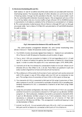
Fig 2. Interconnection between OCs and EIs over OFC
The communication arrangement between OCs and Central Interlocking Units
(CIUs) in Station A – Station B Automatic section is given below.
1. The DOWN direction Automatic Signals from Station A – Station B are controlled by
CIU of Station A with OC placed at Goomties at each location of signal.
2. Thus a, total 4 OCs are connected to Station A CIU corresponding to G-3, 4, 5 and
one OC is placed at Station B to gather the information of Station B`s Down Home
signal , in order to control the aspect of it`s rear automatic signal. (HYR, HHYR, DYR).
3. Channel A of OC No 24 at Station B is connected to Station A CIU over 4 fibers on UP
direction 24 core fiber (Fiber 9, 10, 11 & 12). These fibers are patched in each and
every location of goomties to have continuity of communication.
4. The architecture of EI provides for 8 number of ports and each port can be connected
with 4 OCs except in case of VDUs where only one VDU can be connected to one
port. The configuration of connection of these 4 OCs to CIU is given in Drawings.
5. The channel-A of 4 OCs is connected to M-0 port of CIU using 4 conductors of fiber,
where primary of one OC is connected to secondary of another OC in cascading way.
Similarly Channel-B of 4 OCs is connected to Channel B of M-0 Port using 4 fiber
conductors.
6. Using this connection configuration, the Down direction OCs of 4 & 5 are cascaded
and their Channel-A is connected to channel A of M-5 port on Up direction 24 fiber
using its 5, 6, 7 & 8 conductors. Similarly Channel-B is connected to channel B of M-
5 port on DN direction 24 fiber using its 5, 6, 7 & 8 conductors. Hence the path
redundancy is achieved by connecting channel-A on UP direction 24 fiber and
Channel-B on DN direction 24 fiber. This arrangement is preferred keeping in view
on the limitation of fibers.
7. In brief, the OC at G - 3 is connected to M-4 port, OCs at G – 4 & 5 are connected to
M-5 port and OC at Station B is connected to M-6 ports of CIU at Station A.
Chapter 20: Automatic Block Signalling Page 428 of 535