
Page 473 - IRSEM_Main Book
P. 473
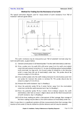
Para No. 19.11.7(d)                                                          Annexure: 19-A3

                                 Method for Finding Out the Resistance of an Earth

                 The  typical  connection  diagram  used  for  measurement  of  earth  resistance  from  ‘Fall  of
                 Potential’ method is given below:


                        The earth resistance may be measured as per ‘fall of potential’ method using four
                 terminal earth tester, as given below:
                        (i)  Connect Current probe C1 & Potential probe P1 to the earth electrode(s) under test.
                        (ii)  Drive a probe onto the earth 30 to 60 meter away from the earth electrode(s)
                            under test and connect to terminal C2. In case of earthing system having multiple
                            earth electrode like ring earth, the Current probe C2 should be in the direction
                            which  is  away  from  the  set  of  electrode(s)  under  test.  This  probe  should  be
                            driven to a depth of 15 to 30 cm.
                        (iii) Drive another probe onto the earth midway between the electrode(s) under test
                            and  probe  C2.  Connect  this  probe  to  terminal  P2.  This  probe  should  also  be
                            driven to a depth of 15 to 30 cm.
                        (iv) Measure the earth resistance. Say it is Reading 1.

                        (v)  Move  the  potential  probe  P2  by  3  meter  farther  away  from  the  electrode(s)
                            under test and do the earth measurement. Say it is Reading 2.
                        (vi) Move  the  potential  probe  P2  by  3  meter  (from  midway)  towards  the  earth
                            electrode(s) under test as shown in figure above and do the third measurement
                            of earth resistance. Say it is Reading 3.
                        (vii) If all the three reading are within a few percent of their average, then average of
                            the three readings may be taken as the earth resistance of electrode(s) under test.

                 Note: In case there is a significant variation of three measurements from their average, then
                 location of test probe C2 may be shifted to a farther distance and test may be repeated.


                                   Chapter 19: Installation, Testing & Maintenance of Signalling Equipment   Page 419 of 535