
Page 464 - IRSEM_Main Book
P. 464
19.11.6 Earth Resistance
Earth Resistance of an 'earth' is the sum of three separate resistances, viz.,
(a) the resistance of the conductor joining the earth electrode to the installation.
(b) The contact resistance between the surface of the earth electrode and the
soil, and the resistance of the body of soil surrounding the earth electrodes.
(c) Normally the first two resistances are negligibly small compared with the
third; so, the resistance of an 'earth' is primarily determined by the nature
of the soil and not by the electrode itself.
(d) The material used for a standard electrode system should be corrosion
resistant. Under ordinary soil conditions, use of galvanized iron or mild
steel electrode is recommended. In cases where soil corrosion is likely to
be excessive, it is preferable to use either copper or copper clad electrode.
The electrodes shall be free from paint, enamel or grease.
(e) Earth tester normally used for measurement of earth resistivity comprises
of the current source and meters in a single instrument and directly read
the resistance value.
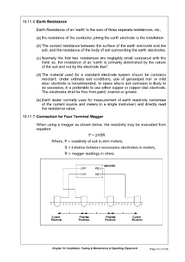
19.11.7 Connection for Four Terminal Megger
When using a megger as shown below, the resistivity may be evaluated from
equation
P = 2πSR
Where, P = resistivity of soil in ohm meters,
S = distance between successive electrodes in meters,
R = megger readings in ohms.
Chapter 19: Installation, Testing & Maintenance of Signalling Equipment Page 412 of 535