
Page 382 - IRSEM_Main Book
P. 382
(h) Flexible coupling between the engine and the alternator shall be checked
for elongated holes and replaced in time.
(i) The no load and on load voltages of the alternator shall be maintained
within limits and the governor shall be adjusted during periodic
maintenance to the RPM specified and for a steady outputof 50 Hz. The
DG set shall be run for 5-10 minutes on load to verify its proper working
during periodic maintenance check.
(j) A log book shall be maintained at every location which shall bear the
history of performance and maintenance of DG set together with the
signatures of Technicians and SSE/JE(Signal).
(k) Wherever auto start is not reliable, the same shall be disconnected and
steps taken for manual start/hand cranking of the generator during power
failure and also to stop the engine as soon as power supply resumes.
Steps shall be taken to rectify the auto start as early as possible.
(l) Adequate number of consumable spares, as required for regular upkeep,
shall be kept ready with the SSE(Signal).
(m)Where standby generators are provided at way side stations/LCs for
signalling purposes and starting and stopping the standby engine is done
by Traffic Staff/ Engineering staff, suitable instructions for maintenance of
fuel account shall be issued locally. The log book shall be maintained by
the ASM/Gate man.
(n) Automatic fire detection and alarm system with or without automatic fire
suppression system (as applicable) may be provided. Firefighting
equipment shall be kept in the power supply equipment room.
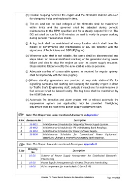
Note: This Chapter has under mentioned Annexures in Appendix-I
S.No Annexure No Description
1 16-MS1 Maintenance Schedules for Integrated Power Supply System.
2 16-MS2 Maintenance Schedules for IPS with Battery Bank Readings.
3 16-MS3 Maintenance Schedules for Discrete Power Supply.
4 16-MS4 Maintenance Schedules for Conventional Power Equipment
(Stabilizer, Charger & Inverter) with Battery bank Readings.
Note: This Chapter has under mentioned Drawings in Appendix-II
Drawing
S. No Description
No
1 16-D1 Scheme of Power Supply Arrangement for Distributed Electronic
Interlocking
2 16-D2 Power Supply Arrangement for Central Electronic Interlocking
3 16-D3 IPS Arrangement for Interlocked LC Gate & IBS
Chapter 16: Power Supply Systems for Signalling Installations Page 330 of 535