Page 195 - IRSEM_Main Book
P. 195

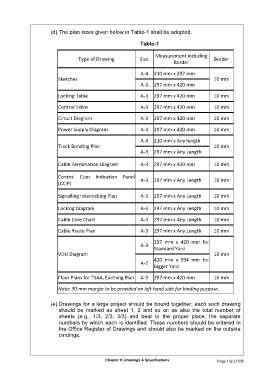
(d) The plan sizes given below in Table-1 shall be adopted.

                                                               Table-1

                                                                      Measurement including
                                    Type of Drawing            Size                             Border
                                                                              Border

                                                               A-4  210 mm x 297 mm
                           Sketches                                                             10 mm

                                                               A-3  297 mm x 420 mm
                           Locking Table                       A-3  297 mm x 420 mm             10 mm


                           Control Table                       A-3  297 mm x 420 mm             10 mm

                           Circuit Diagram                     A-3  297 mm x 420 mm             10 mm

                           Power Supply Diagram                A-3  297 mm x 420 mm             10 mm

                                                               A-4  210 mm x Any length
                           Track Bonding Plan                                                   10 mm
                                                               A-3  297 mm x Any Length

                           Cable Termination Diagram           A-3  297 mm x 420 mm             10 mm

                           Control  Cum  Indication  Panel     A-3  297 mm x Any Length         10 mm
                           (CCIP)

                           Signalling Interlocking Plan        A-3  297 mm x Any Length         10 mm

                           Locking Diagram                     A-3  297 mm x Any Length         10 mm

                           Cable Core Chart                    A-3  297 mm x Any Length         10 mm

                           Cable Route Plan                    A-3  297 mm x Any Length         10 mm

                                                                     297  mm  x  420  mm  for
                                                               A-3
                                                                     Standard Yard
                           VDU Diagram                                                          10 mm
                                                                     420  mm  x  594  mm  for
                                                               A-2
                                                                     Bigger Yard

                           Floor Plans for TSAA, Earthing Plan  A-3  297 mm x 420 mm            10 mm

                           Note: 30 mm margin to be provided on left hand side for binding purpose.

                        (e) Drawings for a large project should be bound together, each such drawing
                           should  be  marked  as  sheet  1,  2  and  so  on  as  also  the  total  number  of
                           sheets  (e.g.,  1/3,  2/3,  3/3)  and  bear  in  the  proper  place,  the  separate
                           numbers by which each is identified. These numbers should be entered in
                           the Office Register of Drawings and should also be marked on the outside
                           bindings.


                                                Chapter 8: Drawings & Specifications              Page 162 of 535
   190   191   192   193   194   195   196   197   198   199   200