
Page 199 - IRSEM_Main Book
P. 199
(xviii) List all Main routes with all overlaps, Calling-On routes & Shunt routes.
(xix) Custody of spare keys.
(xx) Date of all previous references of commissioning the installation with
their sanction numbers and deviations (if any) and date of commissioning.
A sample copy of Signalling Interlocking plan & Control table are at
Annexures in appendix II.
8.1.6 Check and Issue of Drawings
(a) Signalling Interlocking Plans and Locking Tables/Control Tables shall be
checked in full at two levels by officer before they are approved and signed
by an officer in Junior Administrative grade or above, authorised by the
Principal Chief Signal and Telecommunication Engineer.
(b) Cable plans, power supply distribution diagrams etc. shall be checked in full
at two levels by officers before they are approved and signed by Divisional
Signal and Telecommunication Engineer/Senior Signal and Telecommunication
Engineer.
(c) All Circuit Diagrams including those submitted by the contractors or Firms
(including PSUs) shall be checked in full at two levels by officer before they
are approved and signed by Deputy Chief Signal and Telecommunication
Engineer. Detailed wiring diagrams for individual stations prepared on the
basis of approved typical circuit diagrams should be checked in full by an
officer and Divisional Signal and Telecommunication Engineer or Senior
Signal and Telecommunication Engineer who may approve and sign them.
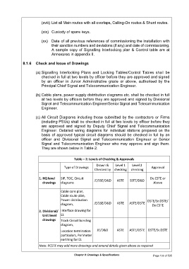
They are shown below in Table-2.
Table – 2: Levels of Checking & Approvals
Drawn & Level 1 Level 2
Type of Drawings Approval
Checked by checking checking
1. HQ level SIP, TOC, Circuit JE/SSE/D&D ASTE SSTE/D&D Dy.CSTE or
drawings diagrams Above
Cable core plan,
Cable route plan,
Power distribution DSTE/Sr.DSTE/
diagram, JE/SSE/D&D ASTE ASTE/DSTE Dy.CSTE
2. Divisional/ Interface drawing for
Unit level EI.
drawings Track Circuit bonding
diagram,
Location termination JE/D&D ASTE ASTE/DSTE DSTE/Sr.DSTE
particulars, Perimeter
earthing for EI.
Note: PCSTE may add more drawings and amend details given above as required
Chapter 8: Drawings & Specifications Page 166 of 535