
Page 60 - IRSEM_Main Book
P. 60
Rail Section BG MG
S/Rail 60Kg 13 mm
(wing rail also) ---
52 Kg 8 mm ---
90 R 5 mm 6 mm
T/Rail 1 60 Kg. 8 mm ---
2 52 Kg/90R 5 mm ---
(v) Measure Lateral Wear of stock and Tongue Rail
S/Rail 8 mm/10 mm max for A, B/Other routes in
straight line
6 mm/8 mm max for A, B/Other route in
curve
T/Rail 60Kg - 8 mm max -----
52Kg/90R - 6 mm max -----
Measure both wears on T/rail at a point with 13 mm head width and at the
point where T/Rail and S/Rail are at the same level
(vi) Check for angular wear of Stock Rail
(vii) Check for clipping of T/Rail within 100 mm (1 Metre ) from toe
(viii) Check for knife-edge of T/Rail within 1 m from toe. If the thickness of the T/Rail
in less than 2 mm continuous for 100 mm (10 Cms) anywhere within 1 meter
from ATS then it is knife edged.
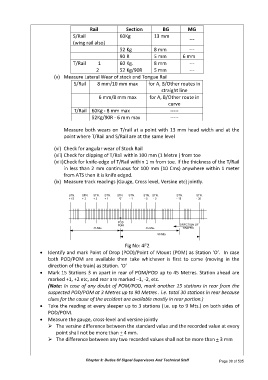
(ix) Measure track readings (Gauge, Cross level, Versine etc) jointly.
STN. STN. STN. STN. STN. STN. STN. STN. STN. STN.
+ 15 + 3 + 2 + 1 '0' - 1 - 2 - 3 - 15 - 30
POD
POM DIRECTION OF
45 Mts. 45 Mts. TRAFFIC
90 Mts.
Fig No: 4F2
Identify and mark Point of Drop (POD)/Point of Mount (POM) as Station ‘O’. In case
both POD/POM are available then take whichever is first to come (moving in the
direction of the train) as Station. ‘O’
Mark 15 Stations 3 m apart in rear of POM/POD up to 45 Metres. Station ahead are
marked +1, +2 etc, and rear are marked –1, -2, etc.
(Note: In case of any doubt of POM/POD, mark another 15 stations in rear from the
suspected POD/POM at 3 Metres up to 90 Metres . i.e. total 30 stations in rear because
clues for the cause of the accident are available mostly in rear portion.)
Take the reading at every sleeper up to 3 stations (i.e. up to 9 Mts.) on both sides of
POD/POM.
Measure the gauge, cross-level and versine jointly
The versine difference between the standard value and the recorded value at every
point shall not be more than + 4 mm.
The difference between any two recorded values shall not be more than + 3 mm
Chapter 3: Duties Of Signal Supervisors And Technical Staff Page 38 of 535