
Page 456 - IRSEM_Main Book
P. 456
19.8.10 Testing Procedure for Panel Interlocking/Route Relay Interlocking
Installations
It shall be ensured that the interlocking system as per approved plans and
drawings. Typical testing procedure for a Relay interlocking installations is
given below with an example for a two line station for an understanding.
(The actual testing at site shall be as per station layout)
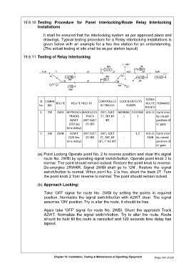
19.8.11 Testing of Relay Interlocking
LOCKS
Sl. SIGNAL CONTROLLED LOCK & DETECTS
ROUTE ROUTE HELD BY ROUTE REMARKS
No. NO. BY TRACKS POINTS
POINTS
1. 2W 2WBI APPROACH BACK LOCK 2WT, A2ET NORMAL REVERSE 4EB 2E Controlled
TRACKS TRACK 2T, 2BT,BT 1 2 by closed
A2WT 2WT A2ET IBT position of
(120 Sec 2T 2BT LC gate
time delay)
2. 2W 2WBII A2WT 2WT A2ET 2WT, A2ET 1,2 4EB 2E Controlled
(120 Sec 2T 2BT 2T, 2BT, BT - 3WB by closed
time delay) IBT, IT A1 WT position of
LC gate
(a) Point Locking Operate point No. 2 to reverse position and clear the signal
route No. 2WBI by operating signal switch/button. Operate point knob 2 to
normal. The point should remain locked. Restore the point knob to reverse.
De-energise 2RWKR. Signal 2WBI shall go to 'ON'. Restore the signal
switch/button to normal. When point No. 2 is free, shunt the track 2T. Turn
the point knob 2 from reverse to normal. The point should remain locked.
(b) Approach Locking:
Take 'OFF signal for route No. 2WBI by setting the points in required
position. Normalize the signal switch/button with A2WT clear. The signal
assumes 'ON' position. Try to alter the route, it should be free.
Again take 'OFF' signal for route No. 2WBI. Shunt the approach Track
A2WT. Normalize the signal switch/button. Try to alter the route. Route
should be held till the route is cancelled and 120 seconds time delay has
lapsed.
Chapter 19: Installation, Testing & Maintenance of Signalling Equipment Page 404 of 535