
Page 435 - IRSEM_Main Book
P. 435
(iv) Each Coil/DP is connected to an Advanced Evaluation Board (AEB) through a surge
protection device, for processing of data received from coil.
(v) Two evaluators (EVs), Main and Redundant (M&R) are provided in IB location as
well as adjacent stations. The main DPs of UP and DOWN direction are connected
to EV(M) and redundant(R) DPs of UP and DOWN direction are connected to EV(R).
The evaluated information is shared to Relay Driver card and COM-AdC. The COM-
AdCs at IB as well as adjacent locations are on a common network through
ethernet ports and in turn through dedicated OFC, via an unmanaged ethernet
switch as shown in Fig.4. The COM-AdCs of both M & R EVs are hot linked and any
failure of one of the board does not hamper the track detection.
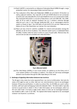
(vi) There are two ethernet switches available for shared communication among the
MSDACs at all the three locations. One ethernet switch works on dedicated fibres
(Tx &Rx). Another ethernet switch works on a pair of quad cable. Alternatively, the
second one can also be provided over redundant fibre.
Fig 6. Ethernet Switch
(vii) The Vital Relays (ACPRs) of each track section are picked up at the Entry end of
track section (either in IB location or station). The status of vital relays exchanged
between two location through IO-EXBs depending on the need.
C. Exchange of signaling information between two locations
The IB signal relay status has to be repeated from rear station to IB location. Similarly the
status of IB signal as well as other vital and non vital indications have to be exchanged
between IB location and Stations. In order to achieve this, the IO-EXBs are used in either
location, with each pair exchanging 3 vital I/Os between them. The vital mode is typically
termed as quad mode in which 3 I/Os of vital information can be exchanged, where as
the non vital mode is termed as single mode, where 12 I/Os can be exchanged between
two locations with a pair of IO-EXBs. The typical Information required to be exchanged
between two locations is as follows.
Chapter 18: Block Instruments, BPAC& IBS Working Page 383 of 535